Special Package System
Skid Mounted Systems
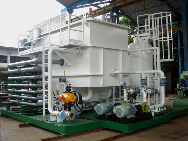
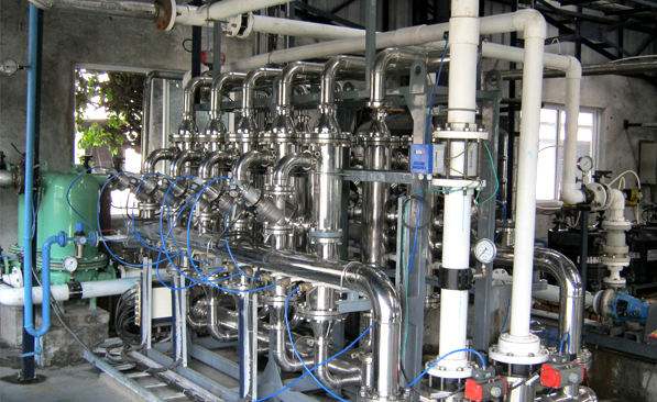
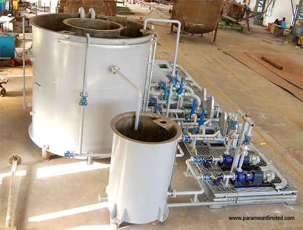
Paramount Limited Supplies skid mounted systems for dosing units (for preparation/ maturing of dosing chemicals), small storage tanks, vessels, skid mounted package units (oil water separators, sewage treatment units, filtration units, Membrane Systems, Condensate Polishing Units etc).
The equipment is fully mounted on a skid with piping, fitting and valves, pumps and motors aligned with cabling up to the starter panel and required instrumentation, control systems like PLC, Analyzers, with cabling up to the junction box is mounted on the skid.

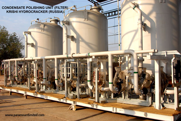
Krishi Hydrocracker (Russia) Condensate Polishing Unit (Filters)
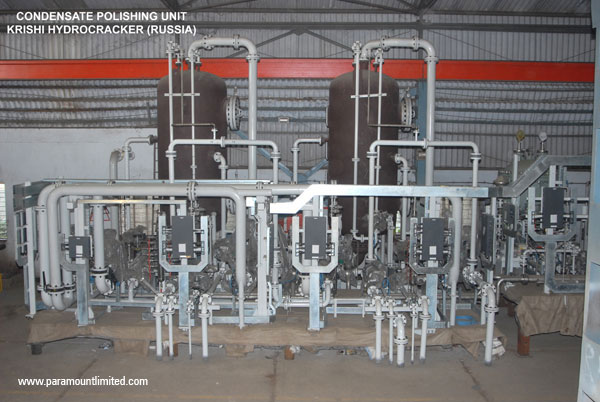
Krishi Hydrocracker (Russia) Condensate Polishing Unit (Mixed Bed Units)
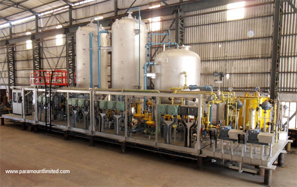
Brahma Putra Gas Cracker (Condensate Polishing Unit)

Doosan Hydro, Dosing Skids

Sandoz, RO Based Two Stage Recycle Plant

Shell LNG Hazira

Assam, Mobile Unit for Produced Water Treatment
Indian Oil Tanking Oily Wastewater Treatment for Tank Farm, Fujairah
Indian Oil Tanking Oily Wastewater Treatment for Tank Farm, Fujairah
Asahi Microfiltration
Package Sewage Treatment Plants
Paramount Limited offers unique package units that are compact and easy to maintain units for treating domestic sewage.
Paramount’s package sewage treatment plants are compact and easy to install and operate in remote areas like oil producing stations, offices, small units, hotels and housing complexes.

Paramount provides Disinfection with chlorination/ ozonation/ UV treatment or its combination as a post treatment scheme of Treated sewage water when water is to be reused.
Package sewage treatment plants are fabricated based on the sewage effluent flow rate and available as “market” units (standard sizes). Being “market” units, standard sizes and models are developed thereby reducing the overall engineering time. This enables Paramount to supply and install these package sewage treatment plants in a short period.
The package sewage treatment plants are offered as,
- Conventional treatment of sewerage water primarily consisting of pre-treatment step to remove grits and large solids, activated sludge process followed by clarification and disinfecting
- Contemporary treatment unit with membrane based activated sludge process (Membrane bio reactors) and disinfecting system
Produced Water Treatment and Re-injection System
The crude oil produced from oil wells is processed at Gas Gathering Stations (GGS) to separate associated gas, crude oil, and water. The separated water called Produced water contains oil and suspended solids which require treatment prior to re-injection into operating or abandoned wells.
Paramount Limited designs, installs and operate the entire range of Produced Water Treatment plant with re-injection system.
Produced water contains free oil, emulsified oil, dissolved and suspended solids.

Paramount Limited designs, installs and operate the entire range of Produced Water Treatment plant with re-injection system.
Produced water contains free oil, emulsified oil, dissolved and suspended solids.
The treatment system comprises of:
• Oily water treatment – API, TPI / CPI separators, DAF units
• SSolids separation – Clarifiers, Clariflocculators, Tube Settlers, Lamella Clarifiers, Thickeners etc
• Filtration – Pressure Filters, Cartridge Filters
• Sludge de-watering system
The oil removed from the system is pumped back to the system for further processing.
The re-injection system consists of specialized high pressure pumps and chemical conditioning system. The filtered treated water is conditioned by chemicals prior to re-injection. The conditioning chemicals dose are selected to prevent corrosion, scaling and biological growth in the Re-injection system. The chemicals are selected after conducting proper treatability studies for the best possible results.
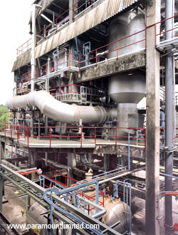
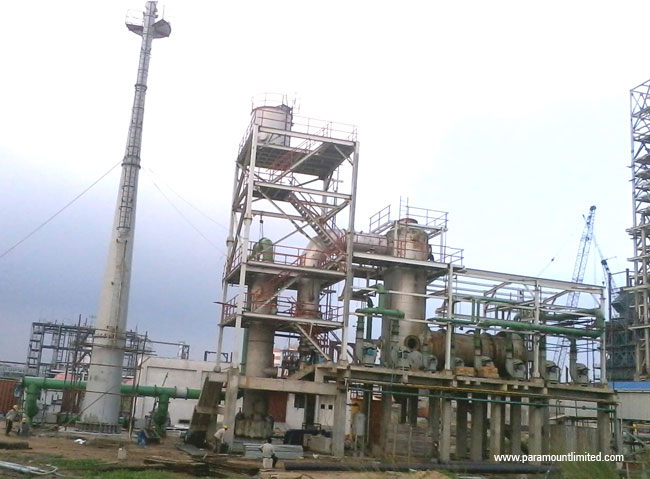
Wet Air Oxidation
Caustic solutions at varying strength are used in the Oil Refinery to clean the various vessels. The Spent Caustic generated contains a high amount of oil & grease, TSS, BOD, COD, sulphide, phenols, mercaptan, sodium thiosulphite, sodium carbonate, sulphates, ammonical nitrogen, TDS etc., and can cause potential damage to the Biological system in an Effluent Treatment plant if mixed with the other oily effluent.
Wet Air Oxidation technology is used in the treatment of Spent caustic generated from the Refinery.

Pre-Treatment:
The spent caustic streams having a high content of organic /acid oils, mainly Naphthenates that are not readily oxidized are responsible for foaming in the typical Wet Air Oxidation Units. Strong acids, such as mineral acids can neutralize such caustic effluents. Typically, concentrated (98 wt %) sulfuric acid (H2SO4) is used to neutralize spent caustic. The H2SO4 reacts with NaOH, sulfides, phenolates, and Naphthenates to form sodium sulfate (Na2SO4), water, H2S, phenols and naphthenic acids respectively. The caustic effluent is typically neutralized at a specific pH range depending on spent caustic composition and availability of treatment facility after the neutralization step.
Neutralized solution may be skimmed to remove the organic layer and then discharged for final treatment in the reaction chamber.
The H2S liberated in the neutralization step is scrubbed through a scrubber column employing H2O2 to trap the sulfur and release the off gas to the atmosphere. The scrubber operates at a low pH and acidic medium, provided for the reaction between the H2O2 and H2S to produce water and sulfur. The products are withdrawn from the column and sent to the oxidation tank in the WAO Unit. The sulfur is filtered out in basket strainers and sent for disposal.
A pre-treatment may also be involved if the main contaminants of the spent caustic stream are oil & grease, sulphide, phenol, organic matters contributing to high BOD and COD, high alkalinity, etc. This stream must be pre-treated before it is finally taken for air oxidation. The pre-treatment steps may necessarily involve removal of free oil and suspended solids if present in the effluent. It is also important that due to the presence of free sodium hydroxide in solution aldol condition may occur due to the polymerization of carbonyls. Furthermore, additional polymerization of dienes is catalyzed by oxygen, oxidizing agents and heavy metal ions.
The organic constituent of the spent caustic is present in two forms: a dissolved phase and a free separate phase. The organic components dissolved in the aqueous phase have different concentrations defined by their solubility limits
On the other hand, the unsaturated hydrocarbons and light aromatic components have significantly higher solubility limits than the saturated and heavy organics. The organics present in the spent caustic beyond their solubility limit in the aqueous phase exist as a separate phase in the form of oily droplets and solid polymer particles that are visible within the spent-caustic solution.
Air Oxidation Process:
After removal of free oil, spent caustic stream is routed to Oxidation Tank. The Wastewater from the Scrubber Column shall also be mixed with the spent caustic stream in the oxidation tank. The spent caustic stream may be further diluted with water to decrease load on the reactor and catalyst solution shall be added. Aeration is also provided in the tank for effective mixing of the incoming streams. This effluent is then pumped to air oxidation system.
The spent caustic is pumped through a Pump to a Guard Filter and the filtered caustic Solution is routed through the Feed / Off Gas Effluent Exchanger where the Off Gas coming out of the Oxidation Reactor cools giving heat to the Feed Caustic Stream. The cooled off gas is sent to the Adsorption Column and the Feed Spent Caustic is sent to the Feed / Effluent exchanger where it picks up heat from the Oxidized Spent Caustic Stream coming from the bottom of the Oxidation Reactor. To achieve the desired temperature of around 130oC at the inlet of the Oxidation Reactor a Steam Heater is normally provided. This heated spent caustic solution is then led to the Oxidation Reactor.
The operating principle is that the waste stream, following preheating, is oxidized in a counter-current method by air in a tray/ packed Reactor to provide intimate contact for sulphide oxidation.
The Caustic stream is fed to the Oxidation Reactor from the top through an inlet distributor. Air inlet is from the bottom of the Reactor from where it passes through the liquid hold up of the Reactor and over to the top through the Trays/ spreaders positioned in the column. The holdup volume in the Reactor provides for sufficient retention time of the air in the system to react with spent caustic.
The off gas from the Oxidation Reactor will contain un-reacted oxygen, carbon dioxide, nitrogen, water vapor and traces of hydrocarbons.
Off gases released from the process before being vented to Atmosphere are cooled in an exchanger and then led to the Gaseous Adsorption Column to retain hydrocarbons and other undesirable compounds, where any remnant hydrocarbons are adsorbed on the activated Carbon bed and the off Gas is thereafter vented to Atmosphere. The temperature is maintained at 140oC and the operating pressure in the Oxidation Reactor is 6.0 Kg/cm2g
Suitable residence time is provided in the Reactor to achieve a high conversion of sulphide. The oxidized caustic product, after passing through conical filters is cooled in the Feed Effluent Heat Exchanger.
Reactions:
1) 2Na2S + 2O2 + H2O –> Na2S2O3 + 2NaOH
2) 2NaRS + 0.5O2 + H2O –>? RSSR + 2NaOH
3) 5Na2S2O3 + 4O2 + H2O –> 5Na2SO4 + 4S + H2SO4
4) 2NaOH + H2SO4 –> Na2SO4 + 2H2O
Post Treatment:
The oxidized caustic solution is then post treated in a Reaction Chamber where it is reacted with Hydrogen Peroxide to remove the remaining sulphides and phenols. The oxidized spent caustic is sent for disposal to sea.
Hazardous Solid & Liquid Waste Incineration
The designs made by Paramount Limited takes advantage of thermal treatment systems custom engineered for incineration of a wide range of industrial hazardous wastes including solid, liquid, sludge, and gaseous waste streams generated by Refineries, petrochemical complexes, pharmaceuticals and bulk drug manufacturing units and chemicals and pesticide units.
Paramount Limited provides you with a single source of expertise for design, engineering, supply and installation of integrated incineration systems.

The incineration systems offered by Paramount are controlled air systems that thermally treat various types of hazardous solid and liquid wastes, sludge. The systems handle waste via a two-stage process. In the primary chamber, the system operates in a sub-stoichiometric mode. Organic materials are heated to a temperature of approximately 750 to 850oC where in organic matter is completely gasified at a controlled Oxygen atmosphere and hence also control possible NOx emissions. In the absence of enough oxygen for complete combustion, volatile gasses are generated for processing in the secondary chamber. The second stage of the process involves oxidizing the products of combustion generated in the primary chamber in an excess air environment in the secondary combustion chamber at 1000 – 1200oC. The resultant gas stream is composed of primarily carbon dioxide and water vapor.
Equipment can process waste at feed capacities from 25 kg/hr up to 1,000 kg/hr on an intermittent or continuous basis.
Paramount designed incinerators can be paired with custom engineered air pollution control systems for a turnkey environmental solution.
Our Incinerator designs incorporate the following types of Incinerator systems.
Rotary Kiln Incinerator Systems:
The rotary Kiln incinerator systems offer maximum flexibility to simultaneously subject thermal oxidation of liquids, solids, and sludges. Rotary kiln incineration systems are ideal for processing mixed industrial and hazardous wastes that include a combination of solid, sludge, and liquid waste streams. Paramount Limited provides complete rotary kiln incineration packages including a broad range of waste storage and feed systems (ram feeders, sludge feed systems, liquid injection systems), complete combustion system packages (burner arrangements), and many different options for continuous ash removal (wet and dry).
Liquid Waste Incineration System:
Effectively incinerate chemical and pharmaceutical liquid wastes. Paramount designs liquid incinerator system in either a horizontal or vertical down fired configuration to meet your unique needs. Each liquid waste combustion system is delivered as a complete solution including combustion system, liquid waste feed system, and controls.
Fume/ Vent Gas Incineration Systems and Thermal Oxidizers:
Effectively process contaminated vent gas and fume streams. Paramount Limited provides a full range of direct-fired thermal treatment systems specifically designed for processing these waste streams. Fume/ vent gas incineration systems are typically designed as two chamber thermal systems. Thermal Oxidizers are designed as a self supporting single chamber thermal system with top mounted vent stack arrangement for the economy.
Incinerators with Heat Recovery Systems:
Add heat recovery to any Paramount design thermal treatment solution. Paramount can engineer thermal treatment system to include heat recovery capabilities. Paramount delivers waste heat recovery system as a completely integrated package including all required ductwork, boiler trim, chemical feed, and de-aerator equipment.
Water tube, panel type, and fire tube style boiler systems are available for the generation of saturated or superheated steam.
Oily Sludge BioRemediation
Growth in population has in turn caused demand for more use of fuel and energy. Petroleum Refineries has stepped into meet the requirement of higher demand for fuel and energy sources. The effect is that more oily sludge generated and requires proper handling to avoid pollution to soil and the underground water table. Pollution control guidelines are evidently strict with respect to handling oily sludge.
Bio Remediation is the only natural way of attending the problems related to the handling of oily sludge.
The Bio-Remediation process is an in-situ biological method to reduce the Total Petroleum Hydrocarbon (TPH) level in the oily sludge to make it suitable for non hazardous land fill site.

The process involves biological processing of the oily sludge in a confined Bio Reactor using special bacterial inoculums and advanced fermentation methods to degrade the petroleum hydrocarbon in the sludge producing a non hazardous sludge with very low level of hydrocarbon. The TCLP analysis of the remediated sludge has to be within US EPA guideline for land fill in a non hazardous site.
The reactor conditions promote the growth of a highly active microbial population which rapidly converts the TPH into carbon dioxide and water.
Paramount Limited with their collaborator offers efficient solutions and suitable and selective inoculums for conversion of oily sludge into bio sludge. The R&D Facility in Paramount Limited conducts suitable treatability studies of oily sludge for selection of the right treatment scheme and the biological culture.
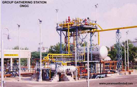
Gas Gathering Station
The quality of crude generation from the oil well is dependent on geological factors. Based on the geological strata wells also generate large volumes of natural gas along with the crude oil pumped out from the oil wells.
Gas gathering stations are installed to separate the oil and gas that are generated from such Oil wells.
Paramount Limited designs and installs Gas Gathering Stations to separate the liquid from the gases that are pumped from Oil producing wells.
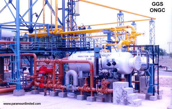
The well fluid as it is pumped out of oil wells are at very high pressures, with the pressure varying due to the depth, quantum of oil production and the ratio of liquid and gas.
The pressure is reduced through a pressure reducing station prior to feeding the two phase fluid in Gas separators. It is essential that the gas separators are maintained at certain optimal pressure for proper phase separation to happen.
After separation, the liquid is subjected to further separation of dissolved gases in a Flash Drum at specifying pressures.
The separated gas from the Flash drum is flared off separately.
Depending on the actual characteristics of the two phase fluid from the oil wells, suitable chemical dosing facility is required. The chemical dosing facilities normally provided are:
• Corrosion inhibitors for the pipelines that carry the fluid
• Antifoam chemicals depending on the foaming tendency
Depending on the sourness of the fluid generated from the oil wells, Caustic soda scrubbing will be required to remove Hydrogen Sulphide content.
Paramount supplies the entire system as a one house design and installation unit with complete automation.
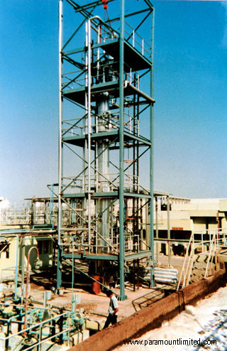
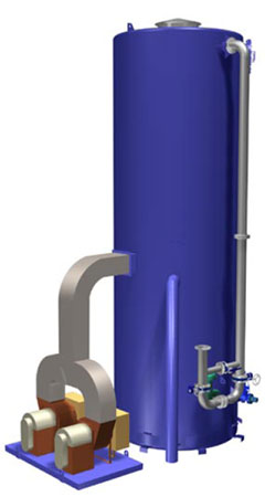
De-Carbonated_Water
The Decabonator removes carbon dioxide produced by the cation exchange process.
The benefits of reducing the carbon dioxide level in feed water minimize the potential of carbonate precipitation of mineral salts. Carbon Dioxide removal also reduces the ionic load on ion exchange processes commonly found in water treatment systems.
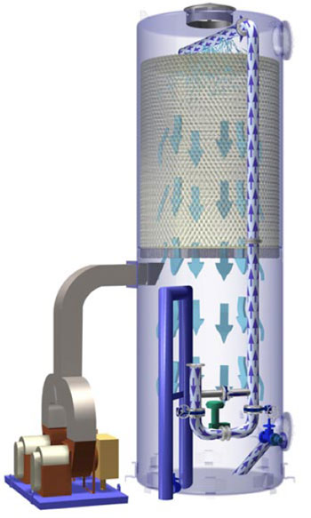
The process involves feeding water into the top of a packed tower at atmospheric pressure while air is forced up from the bottom of the packed tower in a counter-current flow design. The air becomes saturated with CO2 from contacting the water and is removed at the top of the tower.
The packing media in the tower bed typically has a very high surface contact area which enhances the transfer of CO2 from the liquid phase to the gas phase
The pH of the water affects equilibrium between bicarbonate ions and carbon dioxide. At a pH below approximately 4.5, all of the carbon dioxide dissolved in the water is present as a gas. At a pH of about 8.5, all the carbon dioxide is ionized. For this reason, decarbonation by air stripping is only effective at low pH with the pH reduction resulting from a prior process or acid addition.
However, if two-bed deionizers are employed upstream of mixed bed polishers, air stripping may be used after the cation exchanger where the pH is 4.5 or less to remove up 90% of the carbon dioxide gas. The same principal also applies to the downstream treatment of water from reverse osmosis machines. Depending on the percentage of alkalinity relative to other dissolved solids in the raw water, this can increase the capacity of the anion and mixed bed exchangers by several multiples.
Air strippers or decarbonators provide a means to atomize the water, thus increasing surface area, while passing air through the droplets which has a relatively low partial pressure of carbon dioxide (i.e., atmospheric concentration) relative to that of the carbon dioxide entrained in the water.
Decarbonator required ancillary equipment includes pumps to forward treated water to the next process step and blower to remove released carbon dioxide from the tower.
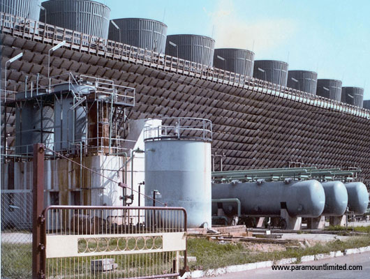
Cooling Tower Blow Down Treatment & Reuse System
Paramount has rich experience & expertise in recycle/reuse solutions for cooling tower blowdown and industrial wastewater.
Normal practice in Industries is the use of fresh water for makeup. Now a days due to shortage of water the recycling concept is immerging in industries. The major contaminants in any cooling tower blow down are suspended solids, some organic matter (BOD and COD), silica, iron and dissolved solids.
So far blow down water is discharged as the above mentioned impurities are not harmful to natural resources up to some limit, hence could be discharged without removal but for reuse it is essential to remove all above impurities as they create problems such as scaling , corrosion, biological contamination and fouling, reaction with other chemicals and changing the quality of product from processes etc. Hence, they need to be removed before reusing.
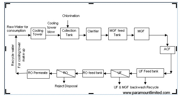
Cooling tower blow down is recycled and reused as makeup water by treating through physico- chemical treatment, clarification, filtration and followed by membrane processes like micro filtration, ultra filtration & reverse osmosis etc.
A Typical cooling tower blow recycle plant
Chlorination:
Chlorination is done for the removal of bacterial growth , organic matter and to oxidize the Iron. It is achieved by the use of oxidizing agents such as chlorine, hypochlorite, chlorine dioxide, etc.
Physico-Chemical Treatment
The Physico-chemical process is done for the removal of reactive silica & suspended solids by the use of coagulant and flocculants. It is carried out by the use of the flash mixture, flocculator followed by Clarifier. The type of clarifier can be selected depending upon the inlet and outlet water quality expected.
Filtration:
Filtration is done for reduction of suspended solids in clarified water to meet the requirement of Ultra filtration membrane system. Thus, it acts as a pretreatment for downstream membrane processes. It is done by use of filters like multi grade filter, dual media filter etc.
Micro filtration (MF) / Ultra Filtration (UF):
Ultra filtration is a tangential flow, low pressure driven membrane process that separates particles on the basis of their molecular size. It removes off the virtually all-particulate matter, suspended solids, bacteria, viruses and pyrogenic species, colloidal material (non-reactive silica etc) and high molecular weight organics. MF/UF also reduces TOC, Colour components, SDI etc. Hence, it is used to improve downstream RO performance with respect to flux rates, recoveries, and reduced maintenance, cleaning frequencies and associated costs.
Reverse Osmosis:
Reverse Osmosis is a high pressure membrane process that rejects practically all soluble impurities present in water, wastewater and process liquids. The process employs a semi permeable membrane that allows selective removal of impurities.
Contact Us At
Address
Paramount Limited, Paramount Complex, Near Natubhai Circle, Race Course, Vadodara, Gujarat - 390007
Phone Number
Vadodara: +91-0265-2397111
+91-0265-6603700
New Delhi: +91-11-26186525, 26186369
Mumbai: +91-22-24078105
Email Address
Vadodara: sales@paramountlimited.com
New Delhi: delhi@paramountlimited.com
Mumbai: mumbai@paramountlimited.com