Biological Treatment
Surface Aerator / Cascade Aerator
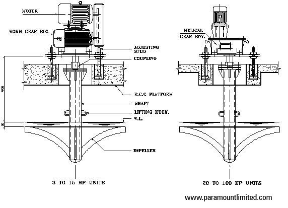
Aerators are used in biological treatment, to convert organic matter into biological cell mass thereby reducing the BOD. Since biological matter consumes dissolved oxygen for respiration; mechanical surface aerators are provided to replenish oxygen thus used up. Aerators are typically used for wastewater applications like sewage and effluent treatment.
Paramount Limited designs & constructs fixed type surface aerators of capacity ranging from 3.0 HP to 100 HP.
Use of Surface aerators in the reduction of BOD is an age old technique. Different designs of surface aerators have been used to improve the aeration of effluent and thereby reduction of BOD and COD.

The types used can be broadly classified as Fixed Type Surface Aerators and Floating Surface Aerators. Fixed type aerators are fixed to RCC structures and connected with operational platforms. Floating type aerators are mounted on platoons that keep the aerators floating. The location of the aerator can be changed by a link arrangement.
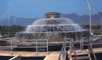
The surface aerators churn the effluent and bring it in contact with atmospheric air as the aeration process. This process poses the limitation of installation of large ponds and large numbers of surface aerators to improve the aeration efficiency. The disadvantage being a high capital cost in building basins, a high operating cost in terms of power consumption and high maintenance cost in terms of periodic cleaning of settled sludge at the bottom of the basin.
Paramount Limited make surface aerator is fixed slow speed type.
The oxygen transfer capacity of the unit shall range from 2.0 kg/kW/hr to 2.1 kg/kW/hr and the minimum ripple velocity at the farthest point would be 0.3 m/sec. The dissipation power will cause the whole mass to remain in the homogeneous condition.
Paramount make surface aerator comprises of:-
Impeller: The aerator impeller is provided with radial self cleaning blades, designed to give optimum oxygen transfer into liquid. The turbulence created by the impeller is sufficient to keep the sludge in suspension at the farthest point. The impeller is normally of mild steel construction (stainless steel impellers are also made) with a tubular shaft designed for required torsional capacity .The wetted parts are suitable for withstanding the corrosive condition of the effluent. The impeller has a self cleaning built in feature, which requires absolutely no maintenance of the impeller since no rags and other solids can get caught within the impeller vanes. The impeller is balanced statically.
Tubular shaft: It is of mild steel pipe (heavy duty) having concentrically machined flanges to connect gear box and motor assembly through rigid heavy duty coupling.
Drive unit: The aerator is driven by a motor of suitable rating. The speed is reduced from the motor speed to the aerator speed by a suitable reduction gear box having worm/helical gears. The speed of the aerator and the diameter of the impeller are so selected that aerator will have the optimum oxygen transfer capacity. The motor is of reputed make suitable for outdoor duties. The reducer bearings and gears are oil lubricated and weather protected.
Our range of manufacturing covers 3.0 HP, 5 HP, 10 HP, 12.5 HP, 15 HP, 20 HP, 25 HP, 30 HP, 40 HP, 50 HP, 60 HP, 75 HP and 100 HP fixed type surface aerators.
Adjusting studs: The depth of submergence can be adjusted by the adjusting studs. It is necessary to maintain the water level to avoid overloading of aerator drive.
Cascade Aerators
Aeration brings water and air in close contact by exposing drops or thin sheets of water to the air or by introducing small bubbles of air (the smaller the bubble, the better) and letting them rise through the water. The scrubbing process caused by the turbulence of aeration physically removes dissolved gases from solution and allows them to escape into the surrounding air.
A cascade aerator (one of the oldest and most common aerators) consists of a series of steps that the water flows over (similar to a flowing stream). In all cascade aerators, aeration is accomplished in the splash zones. Cascade aerators can be used to oxidize iron and to partially reduce dissolved gases.
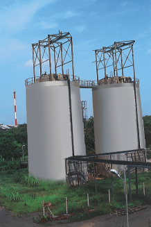
Bio Towers / Trickling Filter
Bio Towers are biological treatment units used widely in effluent treatment plants. Bio towers use plastic media for increasing the specific surface area of the biological action. Bio towers are largely successful wherein the BOD in the effluent is high (as in Refinery effluents) and has advantages on shock loads.
Paramount Limited designs & constructs Bio Tower of all sizes.
Bio towers use plastic media for increasing the specific surface area of the biological action. Bio towers are largely successful wherein the BOD in the effluent is high (as in Refinery effluents) and has advantages on shock loads.

Principle of Operation:
The process of BOD and ammoniacal nitrogen removal is termed ‘biological oxidation’ and is achieved by providing an environment in which both oxygen and organic matter are brought into intimate contact with a population of micro organisms.
The process of ‘biological oxidation’ relies upon naturally occurring micro organisms present in the wastewater adsorbing and subsequently oxidising dissolved organic pollutants from the wastewater in the presence of oxygen.
Effluent is evenly dispersed over the surface of Etapak media by either a rotating or reciprocating distributor. Oxygen is transferred by diffusion from the air (which is continually passing through the media void spaces) into the effluent, which trickles over the media surface. This oxygen supports living micro organisms which feed on the dissolved organic matter in the effluent and grow as a film over the surface of the media.
The biological film is alive and continually growing but, in order for it to stay alive, both the polluting matter, which is the food source, and oxygen must diffuse through its surface to reach all the aerobic micro organisms. Beyond a certain film thickness, the concentrations of food and oxygen become too low to sustain life. At that point, the aerobic organisms starved of food and oxygen die. The dead layer or ‘biomass’ then breaks away (sloughs) from the media surface and is washed down through the Etapak bed. New biofilm now begins to grow on the media surface, becoming progressively thicker, until food can no longer diffuse through it to those layers near the media surface, which therefore die producing more biomass. Thus, the cycle is perpetuated.
Mechanism: Paramount Limited make Bio tower mechanism is a cost effective solution in Biological treatment. The biotower mechanism consists of properly supported distributor arms and rotates on hydraulic power generated by the flow of effluent that is treated in the system.
The distributor arms are provided with nozzles along the length of the arm to evenly spread the effluent across the top layer of the media bed. The flow pattern is selected in such a way to avoid any channeling of effluent in the media bed.
Advantages of “Paramount” make Bio Tower System:
Bio-towers have a proven track record as being robust in withstanding shock organic and hydraulic loads, consequently, complex instrumentation is not required.
The fixed film bio-reactors, as Bio Towers are otherwise called, are predominantly designed to operate on natural draught caused by the small differences in densities of atmospheric air and of the air within the packed bed that is sufficient for ventilation. Where it is considered prudent to install fans, for example bio-reactors treating effluents with process derived odours, the oxygen transfer is such that the cost of installing fans is negligible.
Media bio-reactors are usually 5 – 6 m tall and thus pumps must be employed to raise the effluent and any recycle flow to the liquid distributor. Whilst this pumping consumes some power, the quantities involved are small compared with the savings possible by elimination of activated sludge aeration costs.
The wastage of active cells from a Bio tower is small and thus, no recirculation of biological solids is required.
The sludge from the Bio-tower is stable and shows good settling properties.
Paramount make Media bio-reactors require only occasional monitoring and maintenance.
To sum up:
• Biotower is a conventional equipment and proven technology
• Can absorb shock organic and hydraulic loads
• Economic media cost and replacement easy
• Economical at high BOD content
• Low energy cost compared to other system
• Ease in monitoring and maintenance
A combination of Bio towers and a regular biological treatment (extended aeration) is an alternative solution that provides the twin advantages of energy conservation and absorbing shock loads. The use of bio tower, though not a new technology, in combination with conventional treatment provides with an economical option. The results are proven. Bio towers use plastic media for increasing the specific surface area of the biological action. Bio towers are largely successful wherein the BOD in effluent is high (as in Refinery effluents) and has advantages on shock loads.
Pluses:
• Biotower is a conventional equipment and proven technology
• Can absorb shock loads
• Economic media cost and replacement easy
• Economical at high BOD content
• Low energy cost compared to other system
• Adaptable to conventional and contemporary technologies after Bio-Tower
Bio Towers / Trickling Filter arms
Bio Towers are biological treatment units used widely in effluent treatment plants. Bio towers use plastic media for increasing the specific surface area of the biological action. Bio towers are largely successful wherein the BOD in the effluent is high (as in Refinery effluents) and has advantages on shock loads.
Paramount Limited designs & constructs Bio Tower arms of all sizes.
Bio towers use plastic media for increasing the specific surface area of the biological action. Bio towers are largely successful wherein the BOD in the effluent is high (as in Refinery effluents) and has advantages on shock loads.
Mechanism: Paramount Limited make Bio tower mechanism is a cost effective solution in Biological treatment. The biotower mechanism consists of properly supported distributor arms and rotates on hydraulic power generated by the flow of effluent that is treated in the system.
The distributor arms are provided with nozzles along the length of the arm to evenly spread the effluent across the top layer of the media bed. The flow pattern is selected in such a way to avoid any channeling of effluent in the media bed.
Advantages of “Paramount” make Bio Tower arms:
Bio-towers arms have a proven track record as being robust in withstanding shock organic and hydraulic loads, consequently, complex instrumentation is not required.
Paramount make bio-tower arms require only occasional monitoring and maintenance.
Bio Tower / Media
Plastic Media was first introduced as an alternative to stone in the latter 1950’s and early 60’s. Since then, Plastic Media has been adopted as a standard within the Wastewater Treatment Industry. Different types of plastic media give varying wastewater treatment efficiencies for both BOD and ammoniacal nitrogen removal applications.
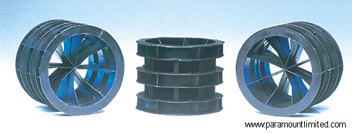
Paramount Limited manufactures poly propylene plastic media for Biotower/ Trickling media filter bed.
Plastic Media was first introduced as an alternative to stone in the latter 1950’s and early 60’s. Since then, Plastic Media has been adopted as a standard within the Water Treatment Industry. Early comparisons showed considerable improvements over stone using simple Plastic Rings. Since then, major developments in shape and profile have lead to even greater improvements.
It is well known that different types of plastic media give varying wastewater treatment efficiencies for both BOD and ammoniacal nitrogen removal applications.
The prime factors affecting specific media performance are :-
• Media Configuration
• Liquid Distribution
• Irrigation Rates
• Liquid Retention Time
• Oxygen Transfer and Sludge Production
• Surface Area Utilization
• Media Volume Requirement
The above factors will primarily determine the capital and operating costs of an effluent treatment Biofilter and are discussed here.
Paramount Limited manufactures ETAPAK coded poly propylene plastic media for Biotower/ Trickling media filter bed.
A typical comparison of Stone media with ETAPAK media manufactured by Paramount is as follow.
Parameter………………………..ETAPAK Media……………………Stone Media
Specific Surface Area…………….100 m2/m3…………………………60 m2/m3
Voidage…………………………………95 %……………………………….50%
Dry Weight……………………………..65 kg………………………………1350 kg
Wet Weight upto…………………….300 kg………………………………1400 kg
The above data equates to the following operational advantages :-
- Higher specific surface area of Plastic Media allows greater hydraulic and organic loadings to be applied, resulting in smaller volume requirements for comparable requirements.
- Higher voidage of Plastic Media reduces the risk of blockage and vastly improves oxygen transfer, resulting in a superior performance of media at high strength loading.
- The lower weight, both dry and operational, reduces loading on tank structure and foundations, reducing capital outlay costs of the plant. The reduced weight of the Media also allows tower height to be increased, reducing the diameter and hence, offering more efficient space utilization.
Media Configuration: Media performance is very much dependant upon its configuration. A high effective surface area, plus good ventilation and liquid distribution must be provided, and the combination of there factors applies to both carbonaceous removal and nitrification. As removal efficiency depends highly upon the rate of diffusion of oxygen and organic pollutant, each element of media surface must be available at the same time and rate to achieve optimum efficiency from a given media volume, by exhibiting an excellent flow of effluent and oxygen in all directions.
The random orientation of ETAPAK Biofilter Media ensures that all media surface is available at the same time for contact between substrate and biomass, thus promoting a high removal rate.
Liquid Distribution: Vertical tube and sheet media depend completely on initial liquid distribution quality at the top of the packed bed. Once the liquid has entered a tube it cannot wet other tubes. A tube or plane which receives no liquid will remain dry throughout its length, hence, the surface area in that tube or plane is lost.
Cross flow sheet media can distribute liquid in one direction and their surface area utilization tends to be, but is not necessarily, better than vertical tube or sheet media.
ETAPAK random media, on the other hand, can distribute liquid in all directions. Consequently, its performance is better than vertical and cross flow sheet media.
Irrigation Rates:As a direct consequence of the inability of sheet media to redistribute liquid, high irrigation rates are required to wet the available surface area. A typical minimum irrigation rate for sheet media is 0.70 gpm/ft2 (1.7 m3/m2.h).
ETAPAK random media has been successfully used with much lower irrigation rates. As a general rule, the minimum irrigation rate for ETAPAK media is 0.2 gpm/ft2 (0.5 m3/m2.h).
The energy required for pumping liquid depends on the volume flow and height the liquid has to be raised. As this is approximately 80% of the total energy requirement of a Biofilter, ETAPAK random media will give significantly tower operating costs.
Liquid Retention Time: ETAPAK random media in a packed bed provides a uniform surface area in three dimensions. This result in greater liquid retention time compared to modular sheet media. Since the contact time between biomass and substrate is related to the liquid residence time a greater removal rate per unit volume (i.e., media surface media) is shown by ETAPAK compared to other media.
Oxygen Transfer and Sludge Production: In all aerobic biological wastewater treatment systems contact between biomass and substrate has to be in the presence of oxygen. Thus, media oxygen transfer efficiency influences performance, in both BOD and ammoniacal nitrogen removal terms. Operation in ETAPAK Biofilters is at near oxygen saturation levels.
Nitrification oxygen demand is more than four times the biochemical oxygen demand. However, ammoniacal nitrogen is not absorbed into the biological floc for later oxidation in contrast to BOD. Therefore, the ammonia must be oxidised during the period it is in the treatment process.
Consequently, sufficient oxygen must be provided to handle the load imposed at all times. The above factors give high nitrogen removal rates in ETAPAK Biofilters.
A further oxygen demand is imposed by endogenous respiration, where approximately 1 kg O2 is required to stabilise 1 lb. of sludge. ETAPAK Biofilter sludge production is approximately 50% of that for modular sheet media. This further indicates the excellent oxygen transfer properties of ETAPAK random media. In addition, sludge treatment and disposal costs are reduced.
Surface Area Utilization: Media performance also depends on how effectively the available surface area is used. Independent analysis has shown that the surface area utilisation of random media is greater than modular sheet media.
Media Volume Requirement: At the end of the day, it is impossible to consider the effects of factors outlined above without appreciating the implication in terms of required media volume. The total installed capital cost is to a great extent dependant upon the size of plant required (i.e., media volume). The media volume is a function of the permissible organic loading for a given BOD removal efficiency.
As a result of the better performance of ETAPAK per unit volume of media, it is possible to specify reduced media volume compared with those required for sheet media of similar specific surface area to achieve the same performance.
In order to illustrate the advantages of ETAPAK media over sheet media quantitatively consider the following example to treat a municipal wastewater.
Average Dry Weather Flow………………..10,000 m3/d
Wastewater Influent after BOD-5…………200 mg/l
Primary Settlement SS……………………..100 mg/l
Wastewater Temperature………………….20 degreeC
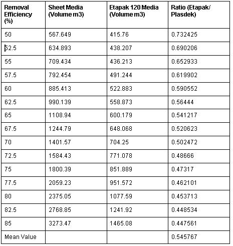
Table 1.0 gives the media volumes required for each type of media for a range of removal efficiencies, the volumes calculated from the design curves. Inspection of Table 1.0 clearly shows that on average, the ETAPAK media volume is only 54.6 percent of the cross flow media volume.
Hence, the capital costs of a Biofilter employing media are considerably lower than a Biofilter using sheet media.
Although the example given above concerns BOD removal, the factors outlined in the various sub-sections above will also determine nitrification performance i.e., the media volume required for a specific nitrogen removal duty will also be considerably lower for ETAPAK compared to cross flow media.
Random Media : ETAPAK 120……………….Specific Surface Area 100 m2/m3
Sheet Media : Cross Flow…………………..Specific Surface Area 100 m2/m3
Example Influent : Type Municipal
Flow: 10,000 m3/day
BOD 200 mg/l
Table 1.0 Media volume required versus BOD removal efficiency
Mechanical Strength of ETAPAK120 versus Sheet Media Filter pack:
As part of an evaluation of the mechanical integrity of ETAPAK 120, independent compression tests were carried out by Rubber and Plastic Research Associates (RAPRA) in its NAMAS TESTING LABORATORY.
The objective was to establish the suitability of ETAPAK 120 for bed heights of 10 m and above.
At the same time, random samples of Sheet Media filterpak were submitted to RAPRA for comparison.
The compression tests were carried out in two principle direction – Vertically and Horizontally. The loads were applied using a top plate of approximately 230 mm square and at a rate of 5 mm / minute until maximum load had been achieved.
As the physical shapes of the two types of packing are very different, the ‘collapsing’ location also varied. However, the overall results were as follows :-
Average Compression Load at ‘Collapse’:
Load Direction……………………Sheet Media (Newtons)………………ETAPAK (Newtons)
Vertical…………………………………….17300……………………………………3350
Horizontal………………………………….231……………………………………….724
Comments:
• As both types of packing are ‘Random’, the weakest point for either packing is in the horizontal mode.
• In the horizontal plane, ETAPAK 120 was over 3 times stronger than Sheet Media filter pack.
• Since the test-work, additional stiffening ribs have been added to ETAPAK 120, to further strengthen the media.
• ETAPAK 120 is suitable for bed heights up to and in excess of 10 m.
Activated Sludge Process
The activated sludge process is a biological wastewater treatment process in which a mixture of wastewater and biological sludge containing a spectrum of micro organisms is agitated and aerated. The biological solids are subsequently separated from the treated wastewater and returned to the aeration process to maintain the required mass of micro organisms for a given application.
The activated sludge process derives its name from the particular biomass formed when the air is continuously injected into the wastewater. In this process, micro organisms are mixed thoroughly with the organics, under conditions that stimulate their growth through the use of the organics as food.

As the micro organisms grow and are mixed by the agitation as food. As the micro organisms clump together (flocculate) to form a suspended culture of biomass termed ‘activated sludge’. In practice, the wastewater flows continuously into an aeration tank where air or oxygen is injected to mix the activated sludge with the wastewater and to supply the oxygen needed for the suspended biomass to break down the organics. In conventional activated sludge systems, the wastewater is aerated for 6-8 hours. The mixture of activated sludge in the aeration tank, termed ‘mixed liquor’, then flows from the aeration tank to a secondary clarifier, where the activated sludge is settled out. A portion of the settled sludge is returned to the aeration tank to maintain the high population of micro organisms necessary for the rapid breakdown of the organics. Because more activated sludge is produced than can be used in the process, some of the return sludge is diverted to the sludge handling system for treatment and ultimate disposal.
Diffused aeration through aeration membrane tubes/ pads/ discs has completely replaced the Surface aerators due to reduced space requirements and improved efficiency factors.
Fine bubble diffuser membranes (fixed type/ removable type/ removable grid type employed) help in providing an even distribution of air to the microbes across the basin. Air is supplied by Aeration blowers and more often the aeration volume is automatically adjusted with the Dissolved Oxygen in the aerated effluent to save power.
The biologically treated effluent is transferred to Secondary Clarifiers.
The sludge from the clarifier is continuously re-circulated to the Activated Sludge process to maintain the MLSS and a part of the bio-sludge is periodically wasted. The wasted bio sludge is de-watered with the de-watered sludge is sent to land fill sites.
Paramount has designed, installed and operated more than 100 Activated Sludge Process biological treatment in varied types of effluents from a multitude of industries including high Nitrate, BOD contaminants.
Extended Aeration Process
The extended aeration process is much similar to the Activated Sludge process. The major difference being that an extended aeration process has a much larger residence time and do not require a primary clarifier unit prior to the biological process. The extended aeration process also generates a good settleable sludge and a clearer overflow compared to the Conventional activated Sludge process. The reduction in BOD and COD is also better than the Conventional activated Sludge process.
Sequential Batch Reactors (SBR)
SBR – Sequencing Batch Reactor technology is well known for its simplicity and low cost. It has been widely used for municipal and industrial wastewater treatment applications or output from anaerobic digesters or mechanical biological treatment to meet specific effluent requirements.
Sequencing Batch Reactor System is a fill and draws Activated Sludge System. SBR process uses high-efficiency oxygen transfer aeration equipment to satisfy the high-rate oxygen consumption requirement at the beginning of the “fill” and “aeration” cycles. SBR is efficient in carbonaceous pollutant removal and is easily modified to satisfy nutrient removal of nitrogen (N) and phosphorous (P). Because the fill, aeration, settlement, and draw take place in the same reaction tank, thus SBR tank itself also serves as the clarifier itself.
")
1")
SBRs produce sludges with good settling properties providing the influent wastewater is admitted into the aeration in a controlled manner.
Paramount Limited provides Sequencing Batch Reactor wastewater treatment plant and process design services, consulting, retrofitting and integration with wastewater treatment units.
Benefit:
• Batch Cycle Adopted With Decantation Avoiding Secondary Clarifier
• Greatly Buffers Shock Loads (Tolerates wide swings in flow and organic loading)
• Flow Equalization
• No Foaming And Bulking
• Co-Current Nitrification, De-Nitrification & Phosphorous Removal (Nutrient removal without chemicals – nitrification and denitrification, phosphate removal)
• Automatic Control On Dissolved Oxygen Possible
• Lower costs than conventional Activated Sludge Process
Limitations:
• Batch Process Involves Additional Reactor Basins
• Due To Batch Process Foot Print Is Larger than MBR systems as the system operates on lower MLSS (~ 3000 mg/l)
• The treated effluent may need to be equalized to ensure the effluent quality is suitable for disposal or for further advanced treatment
• Ultra-filtration Unit To Be Installed Prior To RO Treatment
• Sludge Retention Time (SRT) is limited in comparison to MBR systems as higher SRTs negatively impact the settling of sludge
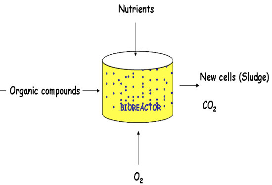
Membrane Bio Reactors (MBR)
Membrane Bio Reactor (MBR) technology is characterized by a combination of biological wastewater treatment (WWT) and membrane separation, by which biomass can be retained in the system without conventional gravity sedimentation. This leads to well-characterized advantages of the technology over conventional activated sludge processes, including smaller reactor footprint, excellent effluent quality, and smaller sludge production.
Paramount designs, integrates and installs MBR system using both flat sheet type membranes and hollow fiber membranes based on system requirement and client’s preferences.
")
Benefit:
• Continuous Process
• Various technologies available – Flat Membrane, Hollow Fibres, Forced Cleaning
• Modular skids available, hence expansion is easier
• Clear permeate water produced thereby reducing filtration step
• The system operates at a higher MLSS of 8000 – 15000 mg/l and thereby reduces the footprint of aeration tanks in comparison to Conventional Activated Sludge Process. It further obliterates the need of secondary clarifier thereby further reducing the overall footprint of the Biological Treatment system
• Can be fed directly for RO treatment. Avoids requirement of pressure filtration units/ Ultrafiltration.
Limitations:
• Continuous air scouring required for biofilm management and to avoid fouling of membrane with solids
• Periodic chemical cleaning of membranes required – Disposal of cleaned waste is a challenge
• Spare membranes are expensive having a guaranteed life of 2 to 3 years
Moving Bed Bio Reactor (MBBR)
Moving Bed Bio Reactor improves reliability, simplify operation and require less space than traditional wastewater treatment system.
MBBR technology employs biofilm carriers in aeration tank / basin. These biofilm carriers increase productivity through providing protected surface area to support the growth of bacteria within it’s cell. This high population of bacteria achieves high rate biodegradation.
This process is used for the removal of organic substances, nitrification, and denitrification.

The MBBR process can be used for a Varity of different applications to attain the desired results, depending on the quality of wastewater and the discharge regulations.
Major Benefits:
• Lower footprint
• Cost Efficient
• Minimize process complexity
• Easy to shipment
• Less time is required at site for installation / erection.
• Less Civil work
As the sewage generation pattern was not regular, to equalize the flow an equalization tank / sump was designed considering peak water flow. The raw sewage shall be collected in a Equalization / Collection Sump. The sewage contains floating solids and to remove floating solids, we provide Screen chamber and also to remove oil from sewage we provide Oil & Grease Trap at the inlet of equalization / collection tank.
Two MBBR reactors were provided in series for better efficiency. The sewage, received at equalization / collection tank shall be pumped to the MBBR reactor. The sewage treatment plant is designed as attached growth aerobic process using floating polypropylene media. The Aeration tank shall operate as Moving Bed Bio Reactor (MBBR). In the MBBR tank, sufficient aeration time shall be provided to obtain good growth of the biomass. The floating media provides sufficient surface for biological growth. The oxygen required for the bio growth shall be provided by the aeration blower provided near the plant. Bubble diffusers in aeration tank shall provide optimum oxygen transfer required for biodegradation of sewage.
Anaerobic Process
Paramount offers anaerobic processes for high BOD effluents that can support the production of biogas.
Paramount design and supply Upflow Anaerobic Sludge Blanket (UASB) Process units.
The UASB process is a biological process in which the organic pollutant present in wastewater is converted into energy rich biogas by bacteria present in the sludge in an anaerobic environment.

The process takes place in a UASB reactor. Wastewater is fed to the bottom of the reactor by means of a specially designed distribution system and passes upwards through the dense granular sludge bed. The pollutants are rapidly converted into methane rich biogas and the treated effluent flows over a weir at the top of the settlers for discharge. The settlers are of special design and ensure a good separation of treated water, biogas and sludge.
Benefit:
• Low investment and operating costs
• Stable and largely automated process control
• Low energy consumption
• Low nutrients requirement
• Loadings of up to 15kg COD per m3 reactor volume per day
• Reactor shutdown for prolonged period does not pose problem
• Limited production of stabilized, easily dewaterable excess sludge
• Absence of odour and noise nuisance
Limitations:
• Special protection due to methane gas is required
• The biogas requires scrubbing prior to use in energy generation to avoid corrosion in the system due to saturated water vapour and Hydrogen Sulphide gas
• Large number of installations are required for higher flow rates
Automated Chemostat Treatment (ACT)
Automated Chemostat Treatment (ACT) is an Aerobic treatment well known for its principle of working – “Low bacteria concentration”. This leads to the well characterized advantage of the technology over conventional activated sludge processes, including a smaller footprint, excellent effluent quality, zero recycle and less sludge production.
It has been widely used for industrial wastewater treatment to meet specific effluent requirements. In a Chemostat reactor influent continuously flows in and out of the reactor and no recycle of sludge takes place in the process. The bacteria’s used in the process are in log phase (young bacteria’s) and hence their metabolic rate is considered to be very high. The log phase bacteria’s grow and multiply fast.
Since influent continuously goes in and out of the reactor, therefore, it is assumed that bacteria’s of average life span are present in the reactor and dead bacteria’s are very less. Sludge wasting period is equal to the retention time of the reactor. The process in Chemostat reactor is independent of F/M ratio, COD, and BOD load. The process in the Chemostat reactor is controlled through a control system which helps in overcoming the COD shock loads.
ACT is used as a first stage biological treatment. The treatment system consists of various process units like Splitter Box, Auto Starter Basin, and ACT Bio Reactor. Primary treated effluent enters the Splitter box of the ACT unit. Underflow and overflow baffles are provided in the Splitter box for better mixing of effluent and nutrients. Nutrients are added in the Splitter box to maintain the bacterial growth. Splitter box splits the effluent equally and overflows into the ACT Bio Reactor by gravity. Fine bubble diffusers are provided at the bottom of the ACT Bio Reactor and continuous aeration is provided by the help of ACT Air Blowers to facilitate the biological activity. Bio-mass recycle is not a requirement for the process as chemostat operates at low biomass concentration (MLSS value of around 100 – 400 ppm dependence on the organic load in the system). Due to the low concentration of bacteria, no aggregates are formed and each bacteria acts as a single unit, increasing the surface area available and achieving optimum biological biodegradation of the organic matter.
The Auto Starter Basin is a safety reservoir for bacteria culture. It shall be utilized when the ACT Bio Reactors are out of order or encounter deterioration in bioremediation performance. Process specific bacteria cocktail isolated from process effluent is prepared and delivered to the Auto Starter Basin as a one time starter. Auto Starter Basin is provided as the stock culture tank with a continuous supply of air from ACT Air Blowers.
Benefit:
• Low bacteria concentration
• No sludge recycle
• Sludge wasting period equals the reactor retention time
• Can sustain high COD fluctuations
• In case of high COD, ACT can be used followed by ASP
• Produces half the amount of bio sludge
• Can react fast to a COD shock load
• Constant stability – no upsets, High quality output
• Lower cost of operation
• Simple auto – control process
Limitations:
• Nutrient requirement may vary depending on the inlet COD load
Contact Us At
Address
Paramount Limited, Paramount Complex, Near Natubhai Circle, Race Course, Vadodara, Gujarat - 390007
Phone Number
Vadodara: +91-0265-2397111
+91-0265-6603700
New Delhi: +91-11-26186525, 26186369
Mumbai: +91-22-24078105
Email Address
Vadodara: sales@paramountlimited.com
New Delhi: delhi@paramountlimited.com
Mumbai: mumbai@paramountlimited.com