Clarifiers and Thickeners
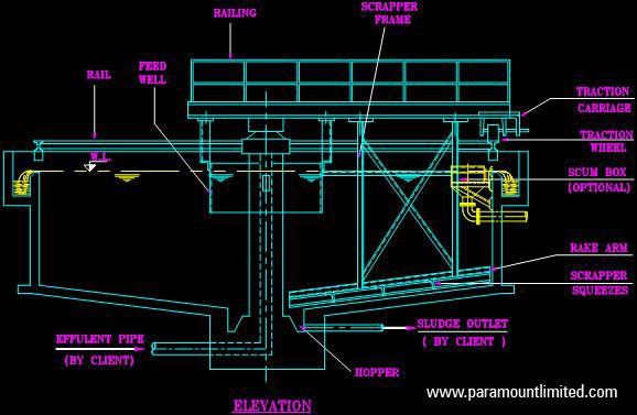
Primary Clarifier
Clarifiers are extensively used to remove suspended solids through gravity settling process with underflow removed from the centrally located solids pocket of the clarifier.
Primary clarifiers are used in the primary treatment section wherein the removal of suspended solids, heavy metallic sludge as in metal/ mineral benefaction units etc is the primary concern. Secondary clarifiers are installed in bio sludge separation units and are not provided with scum separators.
Paramount Limited designs & constructs all types of clarifiers suitable for installation either in RCC/ Steel tank.

Clarifiers are extensively used to remove settled solids through the centrally located solids pocket in both primary and secondary treatment.
Primary clarifiers are used in the primary treatment section wherein the removal of suspended solids, heavy metallic sludge as in metal/ mineral benefaction units etc is the primary concern. Secondary clarifiers are installed in bio sludge separation units and are not provided with scum separators.
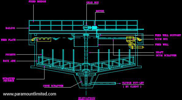
Paramount Limited makes clarifier mechanism which is suitable for installation either in RCC/ Steel tank. The recommended slope is 1:12 at the bottom of the clarifier tank for efficient removal of sludge. The sludge is scrapped from the bottom of the tank by rotating scrapper arm. Primary clarifiers are inbuilt with floating scum separation box and skimmers. The skimmers gently skim the liquid to surface attached to a rotating skimmer arm.
The following models are available.
1 Central driven, bridge supported mechanism
2 Cage driven (Type C) clarifier mechanism
3 Peripheral driven clarifier mechanism
Salient features of Central driven, bridge supported mechanism:

Salient features of Cage driven (Type C) clarifier mechanism:
- A proprietary drive unit comprising of worm and worm wheel gear unit connected to a standard gear box by means of sprockets and chain arrangement and gear box connected directly to the motor.
- A super structure comprising of steel structural bridge spanning up to half the diameter of the tank. The bridge is driven at the centre by a motor and gear box. The bridge is provided with chequered plate/ steel grating. Mild steel hand railing and trolley with steel tyred wheel/ traction wheel on rails. The full bridge can be provided on request.
- The rake arms are suspended from the bridge for efficient raking of solids. The rake arms are provided with brass/ neoprene squeezes and rake the bottom twice per revolution in case of a double scrapper and once per revolution in case of single scrapper.
- Necessary weir plates along with fixing bolts to be fixed to the outlet launder can be provided on request.
- Immersed parts can be provided with lining in rubber/ FRP
- Floating scum scrapper with scum box & high torque switch or torque switch with lifting mechanism can also be provided.

Salient features of Peripheral driven clarifier mechanism:
- Proprietary drive unit consisting of primary cast iron/steel internal spur gear rotated by a secondary worm and worm wheel gear supported on the central RCC column.
- Feed well of suitable diameter is fixed to the bridge is also provided to introduce the feed into the clarifier.
- Access to the drive unit is through a structural steel spanning half the diameter of the tank as per data sheet & is provided with walkway, handrail and foundation bolts for fixing the bridge on tank walls. The full bridge can be provided on request.
- The drive unit rotates the structural steel cage attached to the internal gear and the two rake arms connect to the cage which rakes the tank bottom twice per revolution.
- The feed is let into the clarifier through the hollowed centre column at the bottom or feed pipe at the top. The clarified water is collected through peripheral launder and settled solids through the centre of the tank.
- Necessary weir plates along with fixing bolts to be fixed to the outlet launder can also be provided on request.
- Immersed parts can be provided with lining in rubber/ FRP.
- Floating scum scrapper with scum box & high torque switch or torque switch with lifting mechanism can also be provided.

- A proprietary drive unit comprising of worm and worm wheel gear unit connected to a standard gear box by means of sprockets and chain arrangement and gear box connected directly to the motor.
- A super structure comprising of steel structural bridge spanning up to half the diameter of tank. The bridge is driven at the periphery by a motor and gear box. The bridge is provided with chequered plate/ steel grating. Mild steel hand railing and trolley with steel tyred wheel/ traction wheel on rails. The full bridge can be provided on request.
- The rake arms are suspended from the bridge for efficient raking of solids. The rake arms are provided with brass/neoprene squeezes and rake the bottom twice per revolution in case of a double scrapper and once per revolution in case of single scrapper.
- Necessary weir plates along with fixing bolts to be fixed to the outlet launder can also be provided on request.
- Immersed parts can be provided with lining in rubber/ FRP.
- Floating scum scrapper with scum box & high torque switch can also be provided.
Secondary Clarifier
Clarifiers are extensively used to remove suspended solids through gravity settling process with underflow removed from the centrally located solids pocket of the clarifier.
Primary clarifiers are used in the primary treatment section wherein the removal of suspended solids, heavy metallic sludge as in metal/ mineral benefaction units etc is the primary concern. Secondary clarifiers are installed in bio sludge separation units and are not provided with scum separators.
Paramount Limited designs & constructs all types of clarifiers suitable for installation either in RCC/ Steel tank.
Clarifiers are extensively used to remove settled solids through the centrally located solids pocket in both primary and secondary treatment.
Primary clarifiers are used in the primary treatment section wherein the removal of suspended solids, heavy metallic sludge as in metal/ mineral benefaction units etc is the primary concern. Secondary clarifiers are installed in bio sludge separation units and are not provided with scum separators.
Paramount Limited makes clarifier mechanism which is suitable for installation either in RCC/ Steel tank. The recommended slope is 1:12 at the bottom of the clarifier tank for efficient removal of sludge. The sludge is scrapped from the bottom of the tank by rotating scrapper arm. Primary clarifiers are inbuilt with floating scum separation box and skimmers. The skimmers gently skim the liquid to surface attached to a rotating skimmer arm.
The following models are available.
1 Central driven, bridge supported mechanism
2 Cage driven (Type C) clarifier mechanism
3 Peripheral driven clarifier mechanism
Salient features of Central driven, bridge supported mechanism:
Salient features of Cage driven (Type C) clarifier mechanism:
- A proprietary drive unit comprising of worm and worm wheel gear unit connected to a standard gear box by means of sprockets and chain arrangement and gear box connected directly to the motor.
- A super structure comprising of steel structural bridge spanning up to half the diameter of the tank. The bridge is driven at the centre by a motor and gear box. The bridge is provided with chequered plate/ steel grating. Mild steel hand railing and trolley with steel tyred wheel/ traction wheel on rails. The full bridge can be provided on request.
- The rake arms are suspended from the bridge for efficient raking of solids. The rake arms are provided with brass/ neoprene squeezes and rake the bottom twice per revolution in case of a double scrapper and once per revolution in case of single scrapper.
- Necessary weir plates along with fixing bolts to be fixed to the outlet launder can be provided on request.
- Immersed parts can be provided with lining in rubber/ FRP
- Floating scum scrapper with scum box & high torque switch or torque switch with lifting mechanism can also be provided.
Salient features of Peripheral driven clarifier mechanism:
- Proprietary drive unit consisting of primary cast iron/steel internal spur gear rotated by a secondary worm and worm wheel gear supported on the central RCC column.
- Feed well of suitable diameter is fixed to the bridge is also provided to introduce the feed into the clarifier.
- Access to the drive unit is through a structural steel spanning half the diameter of the tank as per data sheet & is provided with walkway, handrail and foundation bolts for fixing the bridge on tank walls. The full bridge can be provided on request.
- The drive unit rotates the structural steel cage attached to the internal gear and the two rake arms connect to the cage which rakes the tank bottom twice per revolution.
- The feed is let into the clarifier through the hollowed centre column at the bottom or feed pipe at the top. The clarified water is collected through peripheral launder and settled solids through the centre of the tank.
- Necessary weir plates along with fixing bolts to be fixed to the outlet launder can also be provided on request.
- Immersed parts can be provided with lining in rubber/ FRP.
- Floating scum scrapper with scum box & high torque switch or torque switch with lifting mechanism can also be provided.
Proprietary sludge rake driving mechanism fully enclosed in a mild steel housing with all gears and bearings in an oil bath with the proper seal between fixed and rotating parts and with adjustable overload control and load indicator, driving motor, gear box etc.
A similar drive mechanism for a turbine with fully enclosed gears and bearings but without overload control and load indicator.
Turbine with recirculation drum, baffles, and supports. The turbine operates at low tip speeds to prevent excessive agitation and floc break up.
Full/ Half diameter bridge provided with walkway and steel angle/ galvanized iron pipe hand rails extending to an operating platform at the centre. The operating platform provides level walkway and clearance around the drive head.
5. Driving shaft/ cage, rake arms with scrapper blades and brass/ rubber squeezes.
6. Conical reaction chamber supported from the super structure.
7. Inlet pipe positioned underwater and supported from super structure / reaction chamber.
8. Clarified effluent is discharged through peripheral launder via. either a submerged weir effluent collecting launder or radial launders with wall brackets or by a pipe. The outlet launder will serve to discharge the flow.
9. One set of sampling pipe arrangement, to collect the sample from different levels.
10. Immersed parts can be provided with lining in rubber/ FRP
Our Standard Range / Capacity / Size: Up to 75 m diameter
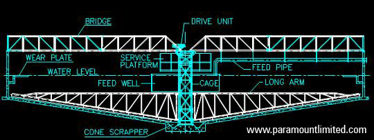
Reaction Clarifier
Reaction Clarifier is mostly used in applications wherein a large variation in the inlet conditions has to be tolerated by the system. Reaction Clarifier produces an effluent of the highest quality in minimum time and space and using a minimum amount of chemicals.
Paramount Limited designs & constructs all types of clarifiers suitable for installation either in RCC/ Steel tank.

Reaction clarifiers (also called High Rate Solid Contact clarifier HRSCC or Solid Contact Clarifier or Solid Contact Clarifier or Sludge Blanket Clarifier) are largely used in pre-treatment of raw water.
Paramount Limited makes clarifier mechanism which is suitable for installation either in RCC/ Steel tank. The recommended slope is 1:12 at the bottom of the clarifier tank for efficient removal of sludge. The unit provides mixing, internal recirculation, flocculation, settling, clarification, positive sludge thickening and removal within a single basin. The sludge is scrapped from the bottom of the tank by rotating scrapper arm.
Raw water enters the primary reaction zone through the inlet into the recirculation drum. Coagulating chemicals may be added in the influent pipe near the point of entry into the recirculation drum. Additional treatment chemicals may also be added in this pipe or directly into the reaction well.
In the recirculation drum, initial mixing and reaction take place in the presence of previously formed floc. The chemicals and recirculated sludge are thoroughly mixed with the raw water by large volume turnover accomplished by the turbine. Further mixing and contact take place in the secondary reaction zone within the reaction well cone, where flocculation is carried to completion in the presence of large quantities of recirculating floc and solids. This treatment ensures thorough chemical mixing and complete floc and precipitates development.
The percentage of solids in the slurry pool within the reaction well may be varied by adjustment of the rotational speed of the turbine and by regulation of the depth and concentration of sludge in the bottom. From the bottom of the reaction well, the flocculated water flows outward and upward where the separation of the floc and water takes place in the outer sedimentation zone. The velocity of the upward flowing clarified water continually diminishes as it rises to discharge into the launder system at the water surface.
Salient features of the mechanism:
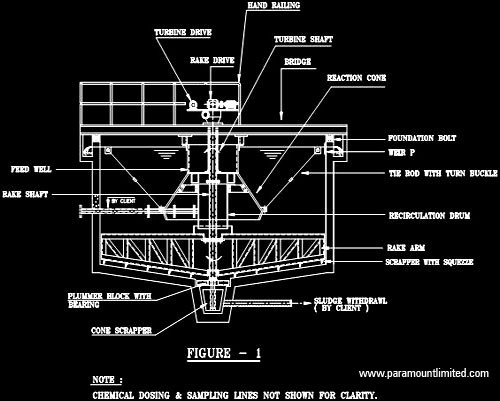
Proprietary sludge rake driving mechanism fully enclosed in a mild steel housing with all gears and bearings in an oil bath with the proper seal between fixed and rotating parts and with adjustable overload control and load indicator, driving motor, gear box etc.
A similar drive mechanism for a turbine with fully enclosed gears and bearings but without overload control and load indicator.
Turbine with recirculation drum, baffles, and supports. The turbine operates at low tip speeds to prevent excessive agitation and floc break up.
Full/ Half diameter bridge provided with walkway and steel angle/ galvanized iron pipe hand rails extending to an operating platform at the centre. The operating platform provides level walkway and clearance around the drive head.
Driving shaft/ cage, rake arms with scrapper blades and brass/ rubber squeezes.
6. Conical reaction chamber supported from the super structure.
7. Inlet pipe positioned underwater and supported from super structure / reaction chamber.
8. Clarified effluent is discharged through peripheral launder via. either a submerged weir effluent collecting launder or radial launders with wall brackets or by a pipe. The outlet launder will serve to discharge the flow.
9. One set of sampling pipe arrangement, to collect the sample from different levels.
10. Immersed parts can be provided with lining in rubber/ FRP
Our Standard Range / Capacity / Size: Up to 75 m diameter
Reaction Clarifier
Reaction Clarifier is mostly used in applications wherein a large variation in the inlet conditions has to be tolerated by the system. Reaction Clarifier produces an effluent of the highest quality in minimum time and space and using a minimum amount of chemicals.
Paramount Limited designs & constructs all types of clarifiers suitable for installation either in RCC/ Steel tank.
Reaction clarifiers (also called High Rate Solid Contact clarifier HRSCC or Solid Contact Clarifier or Solid Contact Clarifier or Sludge Blanket Clarifier) are largely used in pre-treatment of raw water.
Paramount Limited makes clarifier mechanism which is suitable for installation either in RCC/ Steel tank. The recommended slope is 1:12 at the bottom of the clarifier tank for efficient removal of sludge. The unit provides mixing, internal recirculation, flocculation, settling, clarification, positive sludge thickening and removal within a single basin. The sludge is scrapped from the bottom of the tank by rotating scrapper arm.
Raw water enters the primary reaction zone through the inlet into the recirculation drum. Coagulating chemicals may be added in the influent pipe near the point of entry into the recirculation drum. Additional treatment chemicals may also be added in this pipe or directly into the reaction well.
In the recirculation drum, initial mixing and reaction take place in the presence of previously formed floc. The chemicals and recirculated sludge are thoroughly mixed with the raw water by large volume turnover accomplished by the turbine. Further mixing and contact take place in the secondary reaction zone within the reaction well cone, where flocculation is carried to completion in the presence of large quantities of recirculating floc and solids. This treatment ensures thorough chemical mixing and complete floc and precipitates development.
The percentage of solids in the slurry pool within the reaction well may be varied by adjustment of the rotational speed of the turbine and by regulation of the depth and concentration of sludge in the bottom. From the bottom of the reaction well, the flocculated water flows outward and upward where the separation of the floc and water takes place in the outer sedimentation zone. The velocity of the upward flowing clarified water continually diminishes as it rises to discharge into the launder system at the water surface.
Salient features of the mechanism:
Proprietary sludge rake driving mechanism fully enclosed in a mild steel housing with all gears and bearings in an oil bath with the proper seal between fixed and rotating parts and with adjustable overload control and load indicator, driving motor, gear box etc.
A similar drive mechanism for a turbine with fully enclosed gears and bearings but without overload control and load indicator.
Turbine with recirculation drum, baffles, and supports. The turbine operates at low tip speeds to prevent excessive agitation and floc break up.
Full/ Half diameter bridge provided with walkway and steel angle/ galvanized iron pipe hand rails extending to an operating platform at the centre. The operating platform provides level walkway and clearance around the drive head.
Driving shaft/ cage, rake arms with scrapper blades and brass/ rubber squeezes.
6. Conical reaction chamber supported from the super structure.
7. Inlet pipe positioned underwater and supported from super structure / reaction chamber.
8. Clarified effluent is discharged through peripheral launder via. either a submerged weir effluent collecting launder or radial launders with wall brackets or by a pipe. The outlet launder will serve to discharge the flow.
9. One set of sampling pipe arrangement, to collect the sample from different levels.
10. Immersed parts can be provided with lining in rubber/ FRP
Our Standard Range / Capacity / Size: Up to 75 m diameter
High Rate Solid Contact Clarifier (HRSCC)
High Rate Solid Contact Clarifier (HRSCC) is mostly used in applications wherein a large variation in the inlet conditions has to be tolerated by the system. High Rate Solid Contact Clarifier (HRSCC) produces an effluent of the highest quality in minimum time and space and using a minimum amount of chemicals.
Paramount Limited designs & constructs all types of clarifiers suitable for installation either in RCC/ Steel tank.
Reaction clarifiers (also called High Rate Solid Contact clarifier HRSCC or Solid Contact Clarifier or Solid Contact Clarifier or Sludge Blanket Clarifier) are largely used in pre-treatment of raw water.
Paramount Limited makes clarifier mechanism which is suitable for installation either in RCC/ Steel tank. The recommended slope is 1:12 at the bottom of the clarifier tank for efficient removal of sludge. The unit provides mixing, internal recirculation, flocculation, settling, clarification, positive sludge thickening and removal within a single basin. The sludge is scrapped from the bottom of the tank by rotating scrapper arm.
Raw water enters the primary reaction zone through the inlet into the recirculation drum. Coagulating chemicals may be added in the influent pipe near the point of entry into the recirculation drum. Additional treatment chemicals may also be added in this pipe or directly into the reaction well.
In the recirculation drum, initial mixing and reaction take place in the presence of previously formed floc. The chemicals and recirculated sludge are thoroughly mixed with the raw water by large volume turnover accomplished by the turbine. Further mixing and contact take place in the secondary reaction zone within the reaction well cone, where flocculation is carried to completion in the presence of large quantities of recirculating floc and solids. This treatment ensures thorough chemical mixing and complete floc and precipitates development.
The percentage of solids in the slurry pool within the reaction well may be varied by adjustment of the rotational speed of the turbine and by regulation of the depth and concentration of sludge in the bottom. From the bottom of the reaction well, the flocculated water flows outward and upward where the separation of the floc and water takes place in the outer sedimentation zone. The velocity of the upward flowing clarified water continually diminishes as it rises to discharge into the launder system at the water surface.
Salient features of the mechanism:
Proprietary sludge rake driving mechanism fully enclosed in a mild steel housing with all gears and bearings in an oil bath with a proper seal between fixed and rotating parts and with adjustable overload control and load indicator, driving motor, gear box etc.
A similar drive mechanism for the turbine with fully enclosed gears and bearings but without overload control and load indicator.
Turbine with recirculation drum, baffles, and supports. The turbine operates at low tip speeds to prevent excessive agitation and floc break up.
Full/ Half diameter bridge provided with walkway and steel angle/ galvanized iron pipe hand rails extending to an operating platform at the centre. The operating platform provides level walkway and clearance around the drive head.
Driving shaft/ cage, rake arms with scrapper blades and brass/ rubber squeezes.
6. Conical reaction chamber supported from the super structure.
7. Inlet pipe positioned underwater and supported from super structure / reaction chamber.
8. Clarified effluent is discharged through peripheral launder via. either a submerged weir effluent collecting launder or radial launders with wall brackets or by a pipe. The outlet launder will serve to discharge the flow.
9. One set of sampling pipe arrangement, to collect the sample from different levels.
10. Immersed parts can be provided with lining in rubber/ FRP
Our Standard Range / Capacity / Size: Up to 75 m diameter
Sludge Blanket Clarifier
Sludge Blanket Clarifier is mostly used in applications wherein a large variation in the inlet conditions has to be tolerated by the system. Sludge Blanket Clarifier produces an effluent of the highest quality in minimum time and space and using a minimum amount of chemicals.
Paramount Limited designs & constructs all types of clarifiers suitable for installation either in RCC/ Steel tank.

Reaction clarifiers (also called High Rate Solid Contact clarifier HRSCC or Solid Contact Clarifier or Solid Contact Clarifier or Sludge Blanket Clarifier) are largely used in pre-treatment of raw water.
Paramount Limited makes clarifier mechanism which is suitable for installation either in RCC/ Steel tank. The recommended slope is 1:12 at the bottom of the clarifier tank for efficient removal of sludge. The unit provides mixing, internal recirculation, flocculation, settling, clarification, positive sludge thickening and removal within a single basin. The sludge is scrapped from the bottom of the tank by rotating scrapper arm.
Raw water enters the primary reaction zone through the inlet into the recirculation drum. Coagulating chemicals may be added in the influent pipe near the point of entry into the recirculation drum. Additional treatment chemicals may also be added in this pipe or directly into the reaction well.
In the recirculation drum, initial mixing and reaction take place in the presence of previously formed floc. The chemicals and recirculated sludge are thoroughly mixed with the raw water by large volume turnover accomplished by the turbine. Further mixing and contact take place in the secondary reaction zone within the reaction well cone, where flocculation is carried to completion in the presence of large quantities of recirculating floc and solids. This treatment ensures thorough chemical mixing and complete floc and precipitates development.
The percentage of solids in the slurry pool within the reaction well may be varied by adjustment of the rotational speed of the turbine and by regulation of the depth and concentration of sludge in the bottom. From the bottom of the reaction well, the flocculated water flows outward and upward where separation of the floc and water takes place in the outer sedimentation zone. The velocity of the upward flowing clarified water continually diminishes as it rises to discharge into the launder system at the water surface.
Salient features of the mechanism:
Proprietary sludge rake driving mechanism fully enclosed in a mild steel housing with all gears and bearings in an oil bath with a proper seal between fixed and rotating parts and with adjustable overload control and load indicator, driving motor, gear box etc.
A similar drive mechanism for turbine with fully enclosed gears and bearings but without overload control and load indicator.
Turbine with recirculation drum, baffles, and supports. The turbine operates at low tip speeds to prevent excessive agitation and floc break up.
Full/ Half diameter bridge provided with walkway and steel angle/ galvanized iron pipe hand rails extending to an operating platform at the centre. The operating platform provides level walkway and clearance around the drive head.
Driving shaft/ cage, rake arms with scrapper blades and brass/ rubber squeezes.
6. Conical reaction chamber supported from the super structure.
7. Inlet pipe positioned underwater and supported from super structure / reaction chamber
8. Clarified effluent is discharged through peripheral launder via. either a submerged weir effluent collecting launder or radial launders with wall brackets or by a pipe. The outlet launder will serve to discharge the flow.
9. One set of sampling pipe arrangement, to collect the sample from different levels.
10. Immersed parts can be provided with lining in rubber/ FRP
Our Standard Range / Capacity / Size: Up to 75 m diameter
Clariflocculator
In large wastewater treatment plants, the flocculator and the clarifier are combined together to achieve economy in construction. The combined unit of flocculator and clarifier is known as Clariflocculator. It consists of two concentric tanks with inner tank serving as flocculation basin and outer tank serving as clarifier.
Paramount Limited designs & constructs all types of Clariflocculator.

Clariflocculators are used to remove settled solids through the centrally located solids pocket in the flocculator tank located inside the basin.
Paramount Limited make clariflocculator mechanism is suitable for installation either in RCC or Steel tank. The recommended slope is 1:12 at the bottom of the clariflocculator tank for efficient removal of sludge. The sludge is scrapped from the bottom of the tank by rotating scrapper arm.
The following models are available.
1 Turbine types mechanism
2 Central driven mechanism
3 Peripheral driven mechanism
Salient features of Turbine type clariflocculator mechanism:

Two separate drive units are provided for flocculator & clarifier mechanism so that both are operative independently. The drive units are mounted one above another. The rake arms are connected to lower drive unit & turbine type flocculating blades to the upper drive unit. Both the drive units are connected to a motor by standard worm reduction gear box of suitable ratio through flexible coupling/ chain & sprockets to get desired output RPM.
Superstructure comprising of steel structural bridge spanning half/ full diameter of the tank. Necessary chequered plate & hand rails are provided on the bridge so that it can be used as a walkway to have access to the drive unit at the centre.
The drive unit & feed well (mild steel) is fixed at the centre of the bridge which is designed to take a static & dynamic load of the drive unit.
4. The tubular central shaft is connected to adaptor shaft of the drive unit.
5. Two structural steel rake arms are connected to the centre shaft. The rake arms are provided with blades & adjustable brass/neoprene squeezes to rake the tank bottom twice per revolution.
6. The bottom of the shaft rests on guide bearing fixed to the tank cone. Suitable cone scrappers are included in our supply.
7. Feed well of suitable diameter is fixed to the bridge to introduce feed into the clarifier.
8. Necessary weir plates to be fixed to the outlet launder can also be provided
9. Floating scum scrapper with scum box & high torque switch can also be provided.
10. Immersed parts can be provided with lining in rubber/ FRP
Salient features of Central driven clariflocculator mechanism:

Two separate drive units are provided for flocculator & clarifier mechanism so that both are operative independently.
Flocculator drive:
Flocculator drive comprises of a motor connected by worm reduction gear box by a flexible coupling, chain & sprocket to operate at the required speed (revolutions per minute) with suitably sized flocculator paddles that are suspended from the arms of flocculation zone.
Clarifier drive:
- Clarifier drive comprises of a motor connected to worm reduction gear box by chain & sprockets to impart slow motion to the scrapper. Clarifier mechanism is used continuously to remove the settled sludge from the centre of the tank.
- Superstructure comprising of steel structural bridge spanning half/ full diameter of the tank. Necessary chequered plate & hand rails are provided on the bridge so that it can be used as a walkway to have access to the drive unit at the centre.
- The drive unit rotates structural steel cage to which rake arm is attached which rake the bottom of the tank twice per revolution. Rake arm is provided with adjustable neoprene/ brass squeezes for efficient scrapping.
- The drive unit, feed well & rake arms are supported by a structural bridge that is properly supported with the overall unit.
- The bottom of the structural steel cage rests on guide bearing fixed to the tank cone. Suitable cone scrapper is provided.
- The feed is let into the clariflocculator feed well. The clarified water is collected through peripheral launder and settled sludge through the centre of the tank.
- Necessary weir plates to be fixed to the outlet launder can also be provided.
- Floating scum scrapper with scum box & high torque switch can also be provided.
- Immersed parts can be provided with lining in rubber/ FRP.
Salient features of Peripheral driven clariflocculator mechanism:
Two separate drive units are provided for flocculator & clarifier mechanism so that both are operative independently. Flocculator will rotate from the centre while clarifier will rotate from end.
Flocculator drive:
The flocculator drive comprises of motor connected by worm reduction gear of suitable ratio through flexible coupling, chain & sprocket to operate at the required speed (revolutions per minute) with suitably sized flocculator paddles that are suspended from the arms of central flocculation zone made of RCC/ steel.
Clarifier drive:
- Clarifier mechanism is used continuously to remove the settled sludge from the centre of the tank. Clarifier drive comprises of motor connected with worm reduction gear box by chain & sprockets to impart slow motion to the driving steel/ tyred wheel moving on periphery of the clariflocculator tank.
- Superstructure comprising of moving steel structural bridge spanning half the diameter of the tank. The bridge is provided with chequered plate, mild steel hand railing and trolley with steel/ tyred wheel. Full bridge can be provided on request.
- Sludge rake arm is suspended from the bridge (moving) which rakes the tank bottom once every revolution. Sludge rake arm is provided with adjustable brass/rubber squeezes for proper sludge scrapping.
- The feed is let into the clariflocculator by means of hollowed central RCC/ steel column at the bottom. The flocculator drive unit, drive cage and rake arms are supported by central RCC/ steel column.
- Necessary weir plates to be fixed to the outlet launder can also be provided.
- Floating scum scrapper with scum box & high torque switch can also be provided.
- Immersed parts can be provided with lining in rubber/ FRP.
- Telescopic sludge removal arrangement can also be provided.
Thickeners
Thickeners are extensively used to thicken solids & sludge and to remove thickened solids through the centrally located solids pocket at the bottom of the thickener basin. Wastewater treatment plants commonly use thickening devices to increase the solids concentration at the end of a particular process step within the activated sludge process. Thickening aids are often used to improve the gravity separation process.
Paramount Limited designs & constructs all types of thickener mechanism, being suitable for installation either in RCC/ Steel tank.

Thickeners are extensively used to thicken solids and sludge and remove thickened solids through the centrally located solids pocket at the bottom of the thickener basin. Paramount Limited make thickener mechanism is suitable for installation either in RCC/ Steel tank. The recommended slope is 1:12 at the bottom of the clarifier tank for efficient removal of sludge. The sludge is scrapped from the bottom of the tank by rotating scrapper arm.
Salient features of Cage driven thickener mechanism:
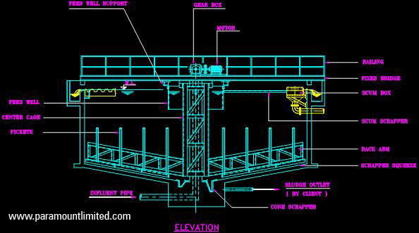
A proprietary drive unit comprising of primary internal spur gear connected to the secondary standard worms and worm reduction gear box by means of sprocket and chain arrangement. The standard gearbox is connected directly to the motor mounted on a mild steel fabricated base frame.
A super structure comprising of steel structural bridge spanning up to half the diameter of the tank. The bridge is driven at the centre by a motor and gear box. The bridge is provided with chequered plate/ steel grating. Mild steel hand railing and trolley with steel tyred wheel/ traction wheel on rails. The full bridge can be provided on request.
The feed is let into the sludge thickener feed well through a hollow centre column or feed pipe at the top. The clarified water is collected through peripheral launder & settled sludge through the centre of the tank.
4. Feed well of suitable diameter is fixed to the bridge to introduce feed into the sludge thickener tank.
5. The drive unit rotates the structural steel cage to which two rake arms are connected which rake the bottom of the tank twice per revolution. The rake arms are also provided with vertical pickets at an equal distance for better sludge compaction.
6. The bottom of structural steel cage rests on guide bearing fixed to the tank cone. Suitable cone scrappers are included in our supply.
7. Necessary weir plates along with fixing bolts to be fixed to the outlet launder can be provided on request.
8. Immersed parts can be provided with lining in rubber/ FRP
9. Floating scum scrapper with scum box & high torque switch or torque switch with lifting mechanism can also be provided.
High Rate Thickeners
High Rate Thickeners are used in quick settleable solids and are predominantly installed in ore benefaction units, metal processing units. It removes thickened solids through the centrally located solids pocket at the bottom of the thickener basin. Thickening aids are often used to improve the gravity separation process.
Paramount Limited designs & constructs High rate thickener mechanism, suitable for installation either in reinforced cement concrete or steel tanks.

High rate Thickeners are used in quick settle-able solids and predominantly installed in ore benefaction units, metal processing units and remove thickened solids through the centrally located solids pocket at the bottom of the thickener basin.
Paramount Limited makes High rate thickener mechanism which is suitable for installation either in reinforced cement concrete or steel tanks. The recommended slope is 1:12 at the bottom of the clarifier tank for efficient removal of sludge. The sludge is scrapped from the bottom of the tank by rotating scrapper arm.
Salient features of High rate thickener mechanism:
Proprietary drive unit consists of a gear mounted on a large diameter strip liner ball bearing driven by a hardened steel worm through a reducer and enclosed chain.
A super structure comprising of steel structural bridge spanning up to half the diameter of the tank. The bridge is driven at the centre by a motor and gear box. The bridge is provided with chequered plate/ steel grating. Mild steel hand railing and trolley with steel tyred wheel/ traction wheel on rails. The full bridge can be provided on request.
3. All gearing components are enclosed in a dust tight cast iron housing with oil bath lubrication.
4. Two long raking arms and two short arms with a slope of 1.75 inches per foot are provided with sufficient blades to scrape the tank bottom twice per revolution.
5. The feed well is fitted with cage.
6. The cone scrapers are attached to a cage-driving shaft. The cone scrapper is designed to fit the desired degree of slope of the discharge cone.
7. A motorized semi-automatic lifting device to provide an automatic lift under high torque conditions.
8. Floating scum scrapper with scum box & high torque switch or torque switch with lifting mechanism can also be provided.
Picket Fence Thickeners
Paramount Limited makes Picket fence thickener mechanism suitable for installation either in reinforced cement concrete or steel tanks. The recommended slope is 1:12 at the bottom of the clarifier tank for efficient removal of sludge. The sludge is scrapped from the bottom of the tank by rotating scrapper arm.

Paramount Limited make Pickets fence thickener mechanism which is suitable for installation either in reinforced cement concrete or steel tanks. The recommended slope is 1:12 at the bottom of the clarifier tank for efficient removal of sludge. The sludge is scrapped from the bottom of the tank by rotating scrapper arm.
Salient features of Picket Fence thickener mechanism:
A proprietary drive unit comprising of worm and worm wheel gear unit connected to the standard gearbox by means of sprocket and chain arrangement. The gearbox, in turn, is connected directly to motor mounted on a mild steel fabricated base frame.
A super structure comprising of steel structural bridge spanning up to half the diameter of the tank. The bridge is driven at the centre by a motor and gear box. The bridge is provided with chequered plate/ steel grating. Mild steel hand railing and trolley with steel tyred wheel/ traction wheel on rails. The full bridge can be provided on request.
The tubular centre shaft is connected to the adapter shaft of the drive unit.
4. Two structural steel rake arms are connected to the centre shaft. The rake arms are provided with blades and adjustable brass/neoprene squeezes to rake the tank bottom twice per revolution. The rake arms are also provided with specially designed vertical pickets for efficient compaction of sludge.
5. The bottom of the shaft rests on guide bearing fixed to tank cone. Suitable cone scrapers are included in our supply.
6. Feed well of suitable diameter is fixed to the bridge is also provided to introduce the feed into the thickener.
7. Necessary weir plates along with fixing bolts to be fixed to the outlet launder can also be provided on request.
8. Floating scum scrapper with scum box & high torque switch or torque switch with lifting mechanism can also be provided on special request.
TPS (Tilted Plate Solid) Separators
Lamella Clarifier is a compact, inclined plate type of clarifier. The main advantage of Lamella Clarifer is its compact size compared to conventional clarifer. It is used for clarification of water, wastewater and liquid having suspended and colloidal particles. Flocculating and coagulating aids are dosed for better performances.
Paramount Limited designs & constructs Lamella Plate Interceptor for suspended solids which are also called as TPS (Tilted plate solid separator).
")
Paramount offered lamella plate interceptor for suspended solids is called a TPS (Tilted plate separator). TPS or lamella separators or Lamella clarifiers are widely used in Raw water treatment processes and provides a compact design in comparison to Tube settler.
The basic principle of difference in gravity between the phases (liquid – liquid, solid – liquid) is employed in the separation of the two phases. This phenomenon is defined as “Gravity Separation”.
It is, therefore, apparent that the phase with high density will settle and with lower density float to the surface of fluid. However, the effectiveness of this technique is subjected to various factors such as the difference in the density, viscosity, factors of the medium, temperature, turbulence, and also the nature of impurity etc.
In some cases, chemical coagulation and flocculation are needed for removal of the impurity by making them heavier or lighter.
In separation technique while considering the above referred factors, which affects the separation of impurities, an overflow rate (m3/m2/day) or settling velocity (m/hr) is arrived at. This factor determines the surface area required for the gravity separation. Incidentally, it proves the fact that it is independent of the depth of basin.
The Tilted plate pack (TPS) separator offered by Paramount with technology acquired from M/s. PWT, Holland provides an extensive reduction in surface area requirement of a separator by introducing multi layer separation wherein area required is reduced considerably depending upon a number of such layers. It is feasible to achieve almost complete removal of all the particles which would not have normally be achieved by a single large surface separator. This is possible because of a considerable increase in the surface area of the unit, within the same depth. In most of the cases, the plates are installed at an angle of 60° or less (but above 50o) and thus the separated material can be collected and removed by gravity.
Paramount has specialized in the design of TPS separator installation in both RCC (Reinforced cement concrete) and steel basins. The selection of the basin of the TPS separator is advised to the client based on the basic requirement, adaptability, time and economy criteria envisaged in the suspended solids treatment process installed.
In larger units, a screw augur at the bottom of the basin is provided to facilitate removal of the settled solids. Sludge is then sent for further treatment in a de-watering facility.
In order to reduce the frictional resistance between the separated material and the corrugated plates to a minimum, particular attention is paid to the smoothness and hardness of the plate surface. The corrugated plates, as well as the casing, are made from glass fiber reinforced isophthalic polyester resin. This material is resistant to most frequently used chemical additives and temperature.
Our Standard Range / Capacity / Size – 2 m3/hr to 2000 m3/hr flow.
Tube Settlers
Tube settlers are gravity settlers wherein the settler is provided with tubes to increase the surface area of separation of solids from the liquid.
Paramount Limited designs & constructs all types of Tube Settlers.
Tube settlers are gravity settlers wherein the settler is provided with tubes to increase the surface area of separation of solids from the liquid. The tubes are placed in an inclined fashion.

The basic theory of tube settlers is that it reduces the detention period to few minutes and achieves the required settling of the turbidity in comparison with conventional settling basin having detention period of 1-4 hrs. This is possible because of the vast area for settlement offered by the tubes installed within the clarifier unit. The area of settling basin is reduced with the high over flow rates viz. to the extent of two to three times higher than convention basins.
The flocculated water is fed into the feed basin centrally located in the gravity settler. The Tube settler is characteristically provided with steep bottom hoppers.
Heavy flocs will settle faster in the hopper of the tube settler while the light particles enter the inclined tubes. Due to a very low velocity of particles inside the tube and also due to the large surface area of the tube, the flocs agglomerates into the bigger size and slides down from the tubes into the hopper, which is then removed as sludge from the tube settlers.
As the units are provided with steep hoppers, there is no need to provide any sludge scrapping/ collection mechanism. Sludge blow off is affected by the static head of water in the tube settler. Sludge is withdrawn from the bottom of the Tube settlers as underflow and sent to sludge sump for the further de-watering process. The clarified water is obtained as an overflow from the tube settler is sent for further treatment in Sand Filters.
Tube settlers are designed based on specific overflow rates and the settling velocity of the solids. Tube settlers are normally circular units and modular concept cannot be adopted as in Lamella clarifiers.
Tube settlers are tall structures and would hence require a pumping arrangement for feeding effluent/ raw water into the unit.
Tube settlers are largely prevalent in large raw water treatment units and help in minimizing capital cost.
Contact Us At
Address
Paramount Limited, Paramount Complex, Near Natubhai Circle, Race Course, Vadodara, Gujarat - 390007
Phone Number
Vadodara: +91-0265-2397111
+91-0265-6603700
New Delhi: +91-11-26186525, 26186369
Mumbai: +91-22-24078105
Email Address
Vadodara: sales@paramountlimited.com
New Delhi: delhi@paramountlimited.com
Mumbai: mumbai@paramountlimited.com